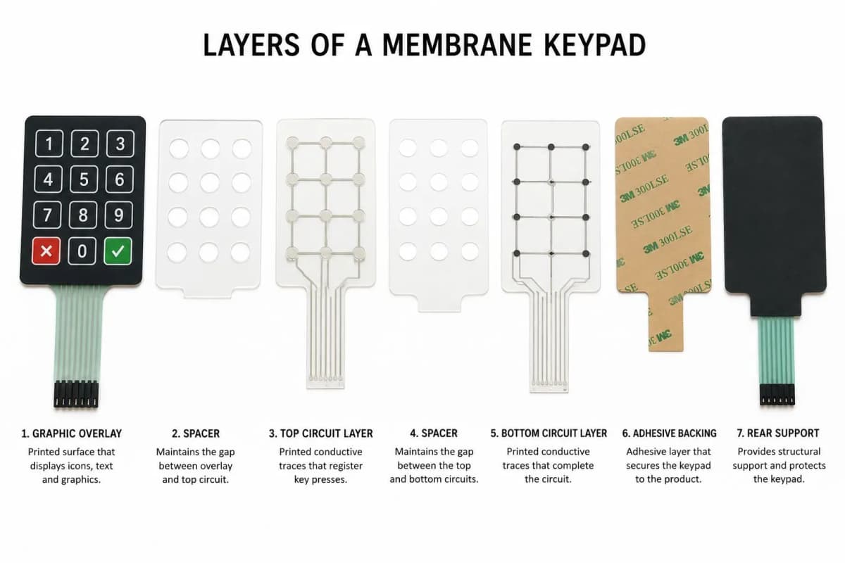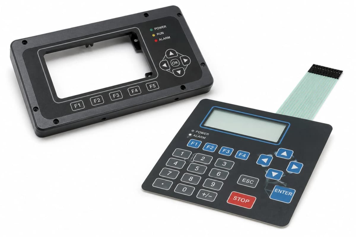
The tail looks like an afterthought. It is a thin strip hanging off the back of the keypad. In practice it is where more field failures start than almost anywhere else in the assembly, and it decides how the keypad connects to the rest of the product.
This guide covers the main tail and connector types, the rules for routing them and how to choose.
Why This Matters
A tail is part of the circuit, not an accessory. Its length, exit position, pitch and termination feed straight into the mechanical design of the enclosure and the layout of the host PCB. Changing them late forces changes in both.
Most tail problems are mechanical: a fold in the wrong place, a connector that does not match the tail thickness, or a bend that cracks printed traces. All are cheap to avoid on a drawing and expensive to fix after tooling.
Key Takeaways
- The tail is part of the circuit and decides how the keypad connects to the product.
- Main termination options: ZIF or LIF connectors, crimped pins with a housing, pin headers, direct soldering and heat seal.
- Match the tail thickness to the connector with a stiffener, and match pitch to the connector exactly.
- Never fold or sharply bend the tail near the keypad body or the contact area.
- Settle tail exit location, length and connector early because they drive both the enclosure and the PCB.
Anatomy of a Tail
A tail normally includes:
- Traces running along its length, printed in conductive ink or etched in copper
- Contact fingers at the end, mating with the connector
- A stiffener under the contact area to set thickness
- Strain relief or a gentle exit radius
- A defined exit point from the keypad body
On printed-ink designs, the contacts are usually overprinted with carbon to resist wear and corrosion. Our guide to circuit types explains why.
Connector Option 1: ZIF Connector
A zero insertion force connector accepts the tail with no pressure. A hinged or sliding latch then clamps the contacts.
Advantages: low wear on the tail, easy assembly, compact, widely available.
Limitations: needs a stiffener to the correct thickness, the latch can be damaged by rough handling, and finer pitch needs careful alignment.
Best for: consumer and industrial products where the tail is plugged onto a PCB.
Connector Option 2: LIF and Slide-In Connectors
A low insertion force connector grips the tail contacts with light spring pressure as it slides in. It has no latch.
Advantages: simple and low cost, tolerant of quick assembly.
Limitations: contact pressure is lower and depends on the stiffener tolerance, so it suits lower-vibration use.
Best for: cost-sensitive products with modest vibration.
Connector Option 3: Crimped Pins and Housings
Metal pins are crimped or clinched onto the tail contacts, then fitted into a plastic housing that plugs into a mating header.
Advantages: robust, good in vibration, easy to unplug, and familiar in harnessed products.
Limitations: added assembly step and cost, larger footprint, and the crimp area needs a flat, stiffened tail.
Best for: industrial, automotive and equipment where connections must be rugged.
Connector Option 4: Pin Headers and Rigid Terminals
A row of rigid pins is attached to the tail contacts, usually at 2.54 mm pitch, and plugs into a socket or is soldered to a board.
Advantages: very simple on the host side, sturdy and easy to prototype.
Limitations: bulky, not suited to fine pitch, and the transition from flex to rigid needs support.
Best for: prototypes, test equipment and larger keypads with few lines.
Connector Option 5: Direct Solder and Heat Seal
Copper FPC tails can be soldered to a PCB. Heat seal, also called hot-bar bonding, uses an anisotropic conductive film that is bonded with heat and pressure, and is common for connecting to displays.
Advantages: compact, permanent, supports fine pitch and low profile.
Limitations: not serviceable, needs process control, and not suitable for printed silver ink tails with solder.
Best for: compact products with a fixed assembly and FPC circuits.
Tail and Connector Types Compared
| Feature | ZIF | LIF / slide-in | Crimped pins + housing | Pin header | Solder / heat seal |
|---|---|---|---|---|---|
| Typical pitch | Fine to medium | Medium | Medium to coarse | Coarse | Fine to medium |
| Stiffener needed | Yes | Yes | Yes | Often | Often |
| Vibration resistance | Fair to good | Fair | Good | Good | Very good |
| Serviceable | Yes | Yes | Yes | Yes | No |
| Footprint | Small | Small | Larger | Larger | Smallest |
| Relative cost | Low to moderate | Low | Moderate | Moderate | Moderate to higher |
Tail Routing Rules
- Exit position. Place the exit where it suits the enclosure, and away from key areas so folds do not stress the switch body.
- Bend radius. Use a generous radius and never form a hard crease. Creases crack printed traces.
- Fold location. Keep folds well away from the keypad edge and from the stiffener.
- Length. Make the tail long enough to assemble comfortably with slack, but not so long it kinks.
- Strain relief. Support the tail near the connector so repeated flexing does not concentrate at its edge.
- Pitch and trace width. Use the coarsest pitch the layout allows, since finer pitch is less tolerant of printing and handling.
- Shield and ground. If the keypad includes shielding, route a ground line through the tail; see our guide to EMI and ESD shielding.
Manufacturing Insight: Request a mechanical mock-up of the tail path in the real enclosure before releasing tooling. A tail that looks fine in CAD can fold badly in an assembled product.
Typical Applications
- ZIF: consumer devices, instruments and industrial controllers plugged straight onto a PCB.
- Crimped pins: industrial and automotive equipment with harness connections.
- Pin headers: test equipment and larger keypads.
- Solder or heat seal: compact FPC designs and display connections.
Common Mistakes
- Mismatching tail thickness and connector. The stiffener must bring the tail to the connector's specified thickness.
- Folding the tail near the body. This is a leading cause of cracked traces.
- Choosing fine pitch without need. It raises cost and handling risk.
- Leaving the exit location open. It forces enclosure changes later.
- Soldering printed silver ink. It does not accept solder; use a connector instead.
- Ignoring ground routing. Shielded designs need a dedicated ground line.
Decision Framework
- Will the tail plug into a PCB socket? Use ZIF with a stiffener.
- Is vibration or rough handling expected? Choose crimped pins with a housing.
- Is it a prototype or a low-line-count keypad? A pin header is simple.
- Is the product compact and permanently assembled? Consider FPC with solder or heat seal.
- Is the circuit printed ink? Avoid solder, and use connector-based termination.
- Fix exit location, length, pitch and bend radius on the drawing before tooling.
Frequently Asked Questions
What is a tail on a membrane switch?
The tail is the flexible extension of the circuit that carries signals from the keypad to the host electronics, ending in contacts that mate with a connector, header or solder pad.
What is a ZIF connector and why is it popular?
ZIF stands for zero insertion force. The tail slides in without pressure and a latch closes to clamp it. It protects the contacts from wear and suits repeated assembly.
What pitch should I choose for my tail?
Pitch must match the connector. Common values include 1.0 mm, 1.27 mm, 2.0 mm and 2.54 mm. Choose the coarsest pitch the layout allows.
Why do tails crack or fail in the field?
Most failures come from sharp folds, bending too close to the keypad body or a tight radius that cracks traces. Rounded bends and strain relief prevent most problems.
Do I need a stiffener on the tail?
Usually yes for ZIF and similar connectors. It brings the contact area to the right thickness and prevents folding inside the connector.
Can the tail be soldered directly to a PCB?
Yes on copper FPC tails, but printed silver ink does not take solder, so printed-ink tails use a connector or pins instead.
Conclusion
The tail is a design decision, not a leftover. Match connector, pitch and stiffener, route it with generous radii and settle exit location early. Doing so prevents the cracked traces and fit problems that account for so many keypad failures in the field.
To review a tail design before tooling, contact our engineering team.