

Multi-Layer
Interface Assemblies
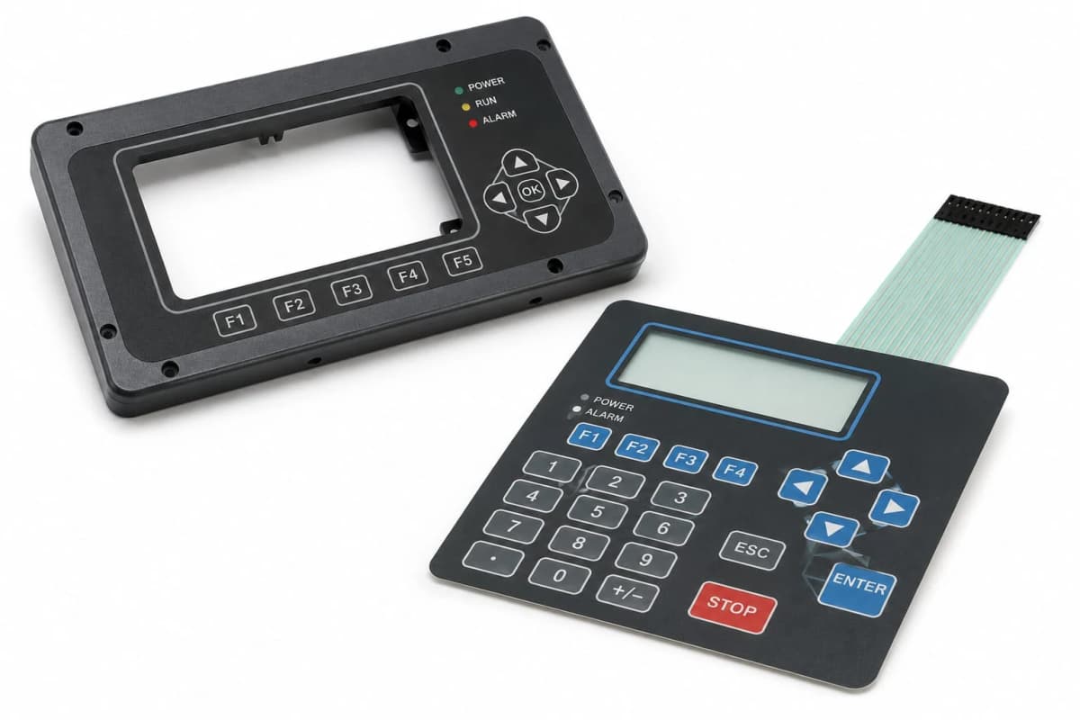
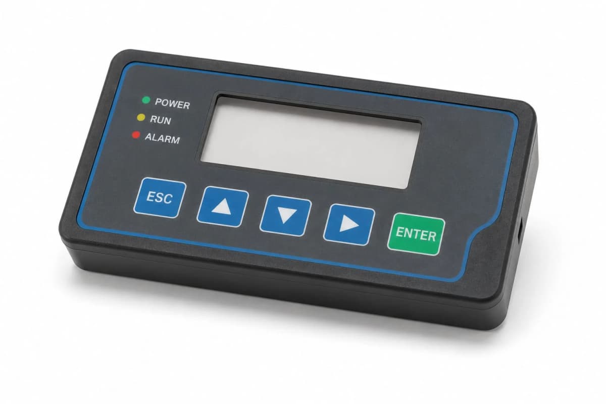
Engineered multi-layer HMI assemblies combining printed graphic overlay, membrane switch circuit, display lens window, backlighting, and machined metal backplate — supplied as a single 100%-tested sub-assembly to your OEM drawing, with layer registration to ±0.1 mm, ZIF/FFC connector tail confirmed to your PCB, and full material certification documentation from our Ahmedabad fabrication facility.
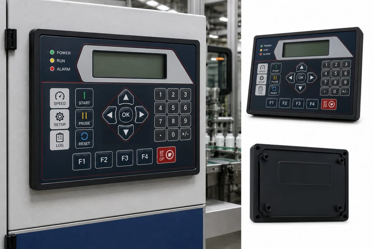
A membrane switch assembly where the overlay legend and the switch dome are misaligned by 0.5 mm is a product defect that cannot be corrected without rebuilding the assembly.
Membrane switch assemblies are precision multi-layer constructions where the spatial relationship between printed legend, switch dome position, and display aperture is fixed permanently at the bonding stage. An assembly built from separately-sourced components — overlay from one supplier, circuit from another, bonded by the OEM's assembly team — achieves registration accuracy that is a function of the OEM's bonding fixture design and the assembly operator's consistency. We bond all layers in a controlled registration fixture that holds every layer to the same reference datum, achieving layer-to-layer registration of ±0.1 mm across every assembly in every production run — not as a specification target, but as a measured and recorded result.
Every assembly 100% electrically tested before it leaves our facility — not sampled, not AQL inspected. Every switch position, every continuity path.
The cost of a failed membrane switch assembly is not the component cost. It is the cost of removing the assembly from the front panel it has already been bonded and sealed to, obtaining a replacement from stock or waiting for a production run, and re-doing the panel assembly operation. We test every assembly on a dedicated electrical test fixture that checks continuity and isolation on every switch position and every circuit path before the assembly is packed — failures are identified and reworked in our facility, not discovered at the OEM's production line or, worse, after the finished product has shipped to the end customer.
One part number. One drawing. One supplier change note for every design revision — regardless of how many layers are in the assembly stack.
A membrane switch overlay assembly typically involves five to eight separate materials: overlay film, conductive ink, adhesive, dome insert, spacer film, rear circuit, connector tail, and backplate. Sourcing these as separate components means five to eight supplier relationships, five to eight incoming inspection records, five to eight change notifications when the design is revised, and five to eight separate quality non-conformance reports when something in the assembly is wrong. We consolidate all of that into a single assembly drawing, a single part number, a single batch record, and a single point of contact for every technical question, quality concern, and delivery schedule discussion.
Assembly Types
Interface Assemblies by Application
Membrane switch overlays, lens-bonded graphic overlays, complete front panel assemblies, backlightable interfaces, IP-sealed HMI panels, and ESD-safe assemblies — each designed, built, and tested to the drawing and compliance requirement of the specific application.
Membrane Switch Overlay Assemblies
Multi-layer membrane switch assemblies integrating a printed graphic overlay, tactile or non-tactile polyester switch circuit, die-cut spacer, and rear circuit layer — supplied as a single bonded assembly with ZIF connector tail for direct PCB connection. Overlay graphics screen or UV-printed to the OEM front-panel drawing, with switch legends, display windows, LED indicator apertures, and port cut-outs all registered to the circuit layer within ±0.1 mm. Actuation force specified to the OEM's ergonomic and tactile feel requirement — from 150 gf non-tactile to 450 gf metal snap dome.
Graphic Overlay with Lens Window
Printed polyester or polycarbonate graphic overlays with integrated display lens windows — bonded clear PC or acrylic lenses registered to the overlay aperture, with anti-reflection or anti-glare coating options for display readability in high-ambient-light environments. Lens bonded with optically clear adhesive that eliminates the air gap between overlay and display surface, eliminating Newton's rings and improving display contrast. The bonded overlay-lens assembly supplied as a single flat component for direct application to the OEM front panel frame.
Front Panel Interface Assemblies
Complete front panel assemblies integrating graphic overlay, membrane switch circuit, display lens window, indicator apertures, and machined aluminium or steel backplate — supplied as a single tested sub-assembly. The backplate CNC-machined to the OEM chassis drawing with connector apertures, PCB mounting pillars, and panel fixing threads all in position — the assembly bolts to the chassis, the PCB connector mates to the membrane switch tail, and the front panel interface is complete without further fabrication at the OEM's assembly stage.
Backlightable Legend Assemblies
Membrane switch and graphic overlay assemblies designed for LED backlighting of key legends, indicator windows, and display surrounds — with translucent ink windows in the overlay, light guide diffuser layers positioned in the assembly stack, and LED apertures in the backplate aligned to the PCB LED positions. Backlight colour, diffusion uniformity, and legend window translucency all specified and sampled prior to production — the backlighted appearance at operating voltage confirmed against the OEM's display specification before the production run is released.
IP-Rated Sealed Interface Assemblies
Membrane switch and overlay assemblies sealed to IP65 or IP67 against ingress of water, cleaning fluids, and particulate contamination — for food processing equipment, outdoor instrumentation, medical device housings, and industrial wash-down environments. Sealing achieved by perimeter channel bonding of the overlay to the panel frame, with a moulded or die-cut gasket bonded to the backplate face for compression against the equipment housing. The IP rating achieved by the assembly construction — not by a post-assembly sealant bead that the end customer must apply.
ESD-Safe & Shielded Assemblies
Membrane switch assemblies with ESD ground plane layers and shielded circuit construction for semiconductor handling equipment, electronics assembly jigs, clean-room instrumentation, and defence electronics front panels where electrostatic discharge from the switch circuit would damage the downstream electronics. ESD ground plane screen-printed into the assembly stack and connected to the chassis ground via the connector tail — the switch circuit effectively shielded from surface charge accumulation by the grounded conductive layer directly beneath the overlay.
Supply Model
Bonded Sub-Assembly vs Separate Components
Both supply models produce the same finished product on the OEM's assembly line. The difference is where the registration, testing, documentation, and change control work happens — in our facility before despatch, or on the OEM's production floor. The comparison below shows what moves when the supply model changes.
| Factor | Sourcing Components Separately | Supplied as a Bonded Sub-Assembly |
|---|---|---|
| Incoming Assembly Work | OEM assembles 4–6 separate components, each sourced individually | Single bonded sub-assembly delivered — one part number, one inbound receipt |
| Layer Registration Accuracy | Registration depends on OEM's assembly jig and operator skill | Layers registered and bonded in controlled fixture to ±0.1 mm |
| Switch Testing | First electrical test at OEM's board-level assembly stage | Every assembly 100% electrically tested before despatch |
| Connector Fit | ZIF connector fit verified at OEM's PCB assembly stage | Connector tail fit confirmed against OEM's PCB connector spec before production |
| IP Sealing | OEM applies sealant bead on assembly line — inconsistent application | Perimeter seal bonded in controlled fixture; IP rating verified on sample |
| Change Control | 6 separate supplier change notes required for a single design revision | Single drawing revision controls the complete assembly specification |
| Traceability | Each component has independent batch traceability; no single assembly record | Single assembly batch record covers all layers, inks, adhesives, and testing |
Construction
Built Layer by Layer
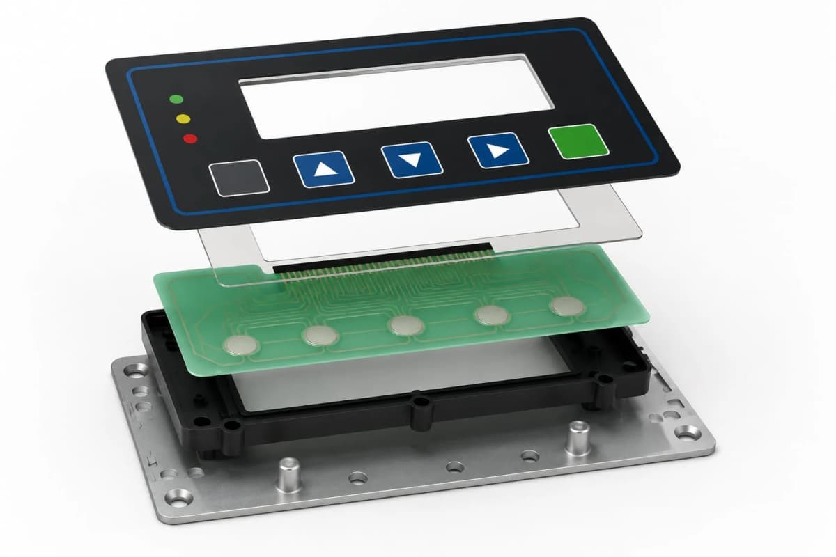
Eight assembly stages — from surface overlay and hard coat through lens window bonding, membrane switch circuit, spacer, rear circuit, structural backplate, and connector termination — each stage executed and inspected before the next layer is bonded.
L-01
Graphic Overlay / Top Skin
Polyester or PC Overlay; Screen / UV Digital Print; Textured or Gloss Finish
L-02
Hard Coat or Protective Laminate
UV Hard Coat; Anti-Glare Laminate; Anti-Static Coating
L-03
Display / Lens Window
Clear Polycarbonate or Acrylic Lens; Anti-Reflection Coating; Tinted Grades
L-04
Membrane Switch Circuit Layer
Silver Conductive Ink on Polyester; Tactile / Non-Tactile; ESD Ground Layer
L-05
Spacer / Air-Gap Layer
Die-Cut Polyester Spacer; Defines Switch Travel and Actuation Force
L-06
Rear Circuit / Backer Layer
Silver or Carbon Ink Bottom Circuit; Ground Plane; Connector Tail Exit
L-07
Structural Backplate
Aluminium, Steel, or GRP Backplate; Machined Apertures; Tapped Insert Fitted
L-08
Connector & Termination
ZIF / FFC Tail; PCB Header; Flying Lead; Gold Contact Finish Available
Technical Parameters
Material & Assembly Specs
Standard parameters across our multi-layer interface assembly range. Values vary by overlay material, switch construction, and connector type — specify your interface envelope, actuation requirement, and operating environment for a confirmed assembly specification.
Materials & Configuration
Built to Your Interface Specification
Overlay material, switch type, actuation force, lens window, backlight, connector termination, backplate material, and hardware — every variable specified to your drawing, your operating environment, and your OEM compliance requirement.
Overlay Materials
Switch Construction
Display & Window Options
Backplate & Hardware
Capabilities
Feature & Build Variants
Overlay material, switch type, print method, lens coating, circuit ink, connector pitch, backplate material, and IP sealing — every variable configured to your drawing and OEM assembly standard.
Production Capability
Built for Serious Production
Layer Registration to ±0.1 mm — Switch Position, Legend, and Lens Aligned in a Single Bonded Operation
A membrane switch assembly where the switch dome position is 0.5 mm out of register with the overlay legend printed above it produces a product that looks correct on the shelf and fails in the field — the operator presses the legend, the dome actuates, but the tactile feedback arrives from a position that doesn't correspond to the visual target. We register overlay, circuit, spacer, and rear circuit layers in a controlled bonding fixture that holds all layers in correct position before the pressure-sensitive adhesive bonds permanently — every layer, every assembly, to the same ±0.1 mm tolerance on all layer-to-layer feature positions.
100% Electrical Test Before Despatch — Every Switch Position, Every Continuity Path, Every Assembly
A membrane switch assembly that arrives at the OEM's production line and fails the first electrical test costs not just the component — it costs the assembly technician time to remove and replace the switch assembly from the front panel frame it has already been bonded to, the front panel if the bonded assembly has delaminated on removal, and the production schedule if the replacement is not in stock. We electrically test every switch position and continuity path on every assembly using a dedicated test fixture before the assembly is bagged and despatched — no sampling, no AQL inspection. Failures are identified and reworked in our facility, not discovered at the OEM's assembly stage.
Connector Tail Specified and Confirmed to the OEM's PCB Connector Before Production Begins
The ZIF or FFC connector tail on a membrane switch assembly must mate correctly with the ZIF socket on the OEM's PCB — correct pitch, correct tail width, correct insertion length, correct contact material, and correct orientation. A tail that is 0.1 mm wider than the ZIF socket clamp will not insert cleanly; a tail with incorrect insertion length will not achieve full contact engagement. We review and confirm the tail specification against the OEM's PCB connector datasheet and, where a PCB layout or connector specification is supplied, produce a pre-production tail sample for connector fit verification before the production tooling is committed.
Complete Assembly Documentation — Material Certs, Test Records, and Artwork Approvals for OEM Quality Files
OEM manufacturers supplying to ISO 13485, AS9100, IEC 61439, or customer-specific quality requirements need complete documentation for every purchased component in their bill of materials. A membrane switch assembly involves overlay film, conductive ink, adhesive, dome, and connector — each with its own material specification and certification requirement. We supply material certifications for overlay, ink, and adhesive; UL94 or RoHS declarations where required; artwork approval records for overlay print; and electrical test reports for each production batch — a complete documentation package that satisfies the OEM's incoming inspection and quality file requirements without requiring the OEM to chase individual material certs from multiple sub-tier suppliers.
Applications
Industries & Applications Served
Wherever a human-machine interface must be precise, durable, sealed, and compliant — from industrial control panels and medical devices through food processing, defence electronics, and outdoor instrumentation.
Custom Fabrication & OEM Range
Related Products
Custom Acrylic Panels
Cast acrylic panels for control room mimic diagrams, HMI fascias, backlit display overlays, and OEM instrument interfaces — second-surface UV print, CNC-routed cut-outs, and opal backlight diffusion construction.
Front Fascia Assemblies
Complete multi-layer front fascia assemblies integrating membrane switch layers, acrylic or polycarbonate overlays, display apertures, and connector termination — supplied as a single fitted assembly.
Polycarbonate Fabricated Components
Precision-fabricated polycarbonate machine guards, flanged enclosure covers, formed housings, and ESD-safe equipment panels — CNC-routed and line-bent to your drawing with hardware fitted for ready-to-install OEM supply.
Every Layer Registered.
Every Assembly Tested.
Share your interface drawing, DXF, or part description — overlay material, switch type, actuation requirement, connector spec, backplate requirement, and quantity — and we'll return a confirmed assembly specification and manufacturing quote.