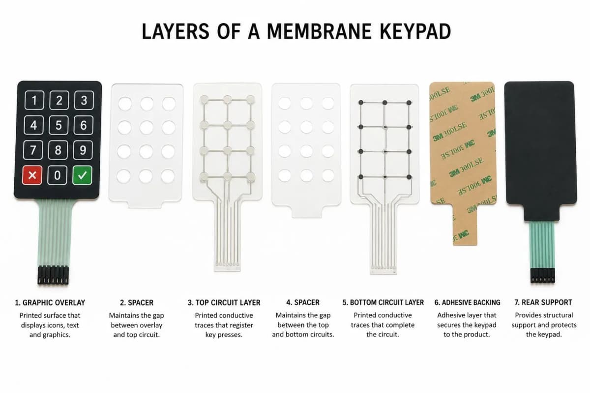
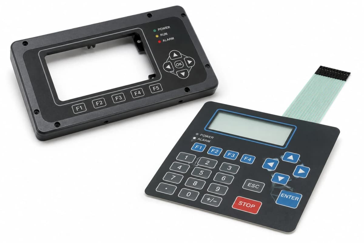
Behind every membrane keypad is a circuit, and the circuit decides what the keypad can carry. A printed-ink flex is thin, cheap and simple. A copper FPC or PCB can mount LEDs and components and route complex signals. Choosing between them is one of the largest cost and capability decisions in the whole design.
This guide explains the four main circuit types, how they differ and where each fits.
Why This Matters
Circuit construction sets the stack thickness, the cost, the options for lighting and shielding, and how the keypad connects to the host. It also sets practical limits: how many lines you can route, how long they can be, and whether components can sit on the keypad.
Because these limits interact with backlighting, connectors and shielding, the circuit type should be settled at the start. Our guides to backlighting options and tail and connector types show how strongly they depend on it.
Key Takeaways
- Four circuit types: printed silver ink, silver with carbon overprint, copper FPC on polyimide and rigid PCB.
- Printed silver on polyester is thin, low-cost and ideal for simple switch matrices.
- Carbon protects contact areas and tails and is standard over silver.
- FPC and PCB support components, LEDs, soldering and fine routing, at higher cost.
- Trace resistance, humidity and bending decide printed-ink limits. Design routing with them in mind.
Type 1: Printed Silver Ink on Polyester
Conductive silver ink is screen printed onto polyester film, then cured. It forms the traces, switch contacts and tail lines.
Advantages
- Very thin and flexible
- Lowest cost for simple circuits
- Short lead time and easy tooling changes
- Proven in high volume
Limitations
- Higher resistance than copper, which limits trace length and width
- Cannot carry soldered components
- Silver can migrate in humidity under bias voltage if unprotected
- Fine features are limited by the printing process
Best for: switch matrices, simple keypads and cost-driven designs.
Type 2: Silver With Carbon Overprint
Here carbon ink is printed over the contact areas and tail fingers, with silver beneath carrying the current. Carbon forms the wear surface.
Advantages
- Protects silver from corrosion and migration
- Good wear resistance at contacts and connector fingers
- Lower contact cost than full silver at the surface
Limitations
- Carbon alone has much higher resistance, so it is used as an overlay or for short links
- Adds a print step
Best for: nearly all printed-ink keypads, especially where humidity or repeated connector use is expected.
Type 3: Copper FPC on Polyimide
A flexible printed circuit uses etched copper traces on polyimide film.
Advantages
- Low resistance and fine-pitch routing
- Supports surface-mounted LEDs, resistors and components
- Can be soldered and withstands soldering temperatures
- Multi-layer routing is possible
Limitations
- Higher material and process cost
- Longer lead time than printed ink
- Copper traces can crack under repeated tight bends if poorly designed
Best for: backlit keypads, component-rich designs and compact products with many lines.
Type 4: Rigid PCB
A conventional rigid board, commonly FR4, can serve as the lower circuit layer beneath a flexible top layer, carrying domes, LEDs, connectors and electronics.
Advantages
- Highest component density and routing capability
- Provides rigidity and flat mounting
- Connectors and LEDs can be mounted directly
Limitations
- Thickest and heaviest construction
- Highest cost and tooling complexity
- Less flexible, so tails need a separate flexible link
Best for: products where the keypad includes electronics, large keypads and designs that mount by screws.
Circuit Types Compared
| Feature | Printed silver | Silver + carbon | Copper FPC | Rigid PCB |
|---|---|---|---|---|
| Base film | Polyester | Polyester | Polyimide | FR4 or similar |
| Relative cost | Lowest | Low | Moderate to higher | Higher |
| Thickness | Thinnest | Thin | Thin | Thickest |
| Supports components | No | No | Yes | Yes |
| Solderable | No | No | Yes | Yes |
| Trace resistance | Moderate | Moderate | Very low | Very low |
| Lead time | Shortest | Short | Longer | Longer |
| Flex tolerance | Good | Good | Good with design care | Poor |
Design Rules That Decide Reliability
Trace Width and Resistance
Printed ink is more resistant than copper, so wide, short traces are better. Keep resistance within the limit the host electronics can tolerate, which should be set on the drawing.
Crossovers and Insulation
Printed circuits cross over using a dielectric insulating layer, which adds cost and a process step. Reducing crossovers simplifies the build.
Humidity and Silver Migration
Silver can migrate between traces under humidity with a voltage applied. Carbon overprint, adequate spacing and protective layers reduce the risk.
Bend Zones
Avoid bending printed or copper traces at tight radii, and keep bends away from the keypad body and connector edge. See tail routing rules.
Contact Design
Contact pad shape, size and surface finish affect contact resistance and bounce. Well-designed pads give stable readings through the product's life.
Manufacturing Insight: If there is any chance of LEDs, a soldered connector or added electronics, begin with FPC or PCB. Converting a printed-ink design later usually means redrawing the stack, not simply swapping a layer.
Typical Applications
- Printed silver and carbon: appliances, instruments, industrial controls and cost-driven keypads.
- Copper FPC: backlit keypads, premium consumer devices and compact electronics.
- Rigid PCB: keypads with embedded electronics, large panels and screw-mounted assemblies.
Common Mistakes
- Starting with printed ink and adding LEDs later. This forces a redesign.
- Skipping carbon overprint. Contacts corrode and wear sooner.
- Routing long, thin traces. Resistance becomes too high.
- Bending tails sharply. Traces crack.
- Ignoring humidity with bias voltage. Silver migration can cause shorts.
- Assuming solder works on printed ink. It does not.
Decision Framework
- Is the circuit a simple switch matrix with no components? Use printed silver with carbon.
- Do you need LEDs, soldered parts or fine routing? Choose FPC.
- Does the keypad carry real electronics or need rigid mounting? Consider a PCB.
- Will the product see humidity? Add carbon overprint and adequate spacing.
- Is resistance critical? Use wider, shorter traces or move to copper.
- Decide this at the start of the design, together with lighting and connection.
Frequently Asked Questions
What are membrane switch circuits made of?
Most are printed with conductive ink on polyester, usually silver with carbon over contact areas. More complex designs use copper traces on polyimide (FPC) or on a rigid PCB.
Why is carbon used over silver ink?
Carbon protects silver contact areas and tail fingers. Silver can corrode or migrate in humidity with applied voltage, while carbon is stable and wear resistant.
When do I need an FPC instead of printed ink?
Choose FPC for surface-mounted components such as LEDs, fine-pitch traces, multi-layer routing or soldered connections.
Is printed silver ink reliable?
Yes when properly designed and cured. Reliability depends on trace width, print quality, carbon protection and avoiding sharp folds or humidity with bias voltage.
Can I solder to printed silver ink?
Generally no. Use a connector, crimped pins or a conductive bond. Copper FPC supports soldering.
What limits circuit trace length?
Trace resistance. Wider traces, silver rather than carbon and shorter routing keep resistance within limits.
Conclusion
Circuit type is a capability decision as much as a cost decision. Printed silver with carbon is the efficient default, FPC unlocks LEDs and components, and a rigid PCB supports full electronics. Decide early, set resistance limits on the drawing and design bends and contacts for the long term.
To review a circuit choice, contact our engineering team.